Omega (Ω) Steel Arches
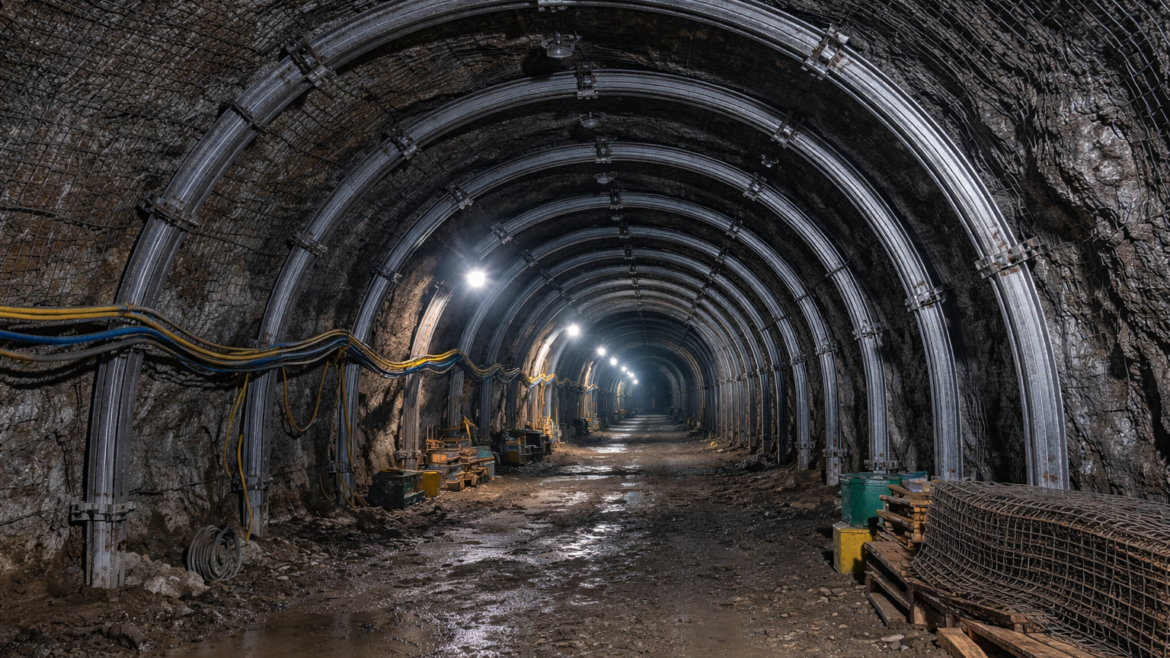
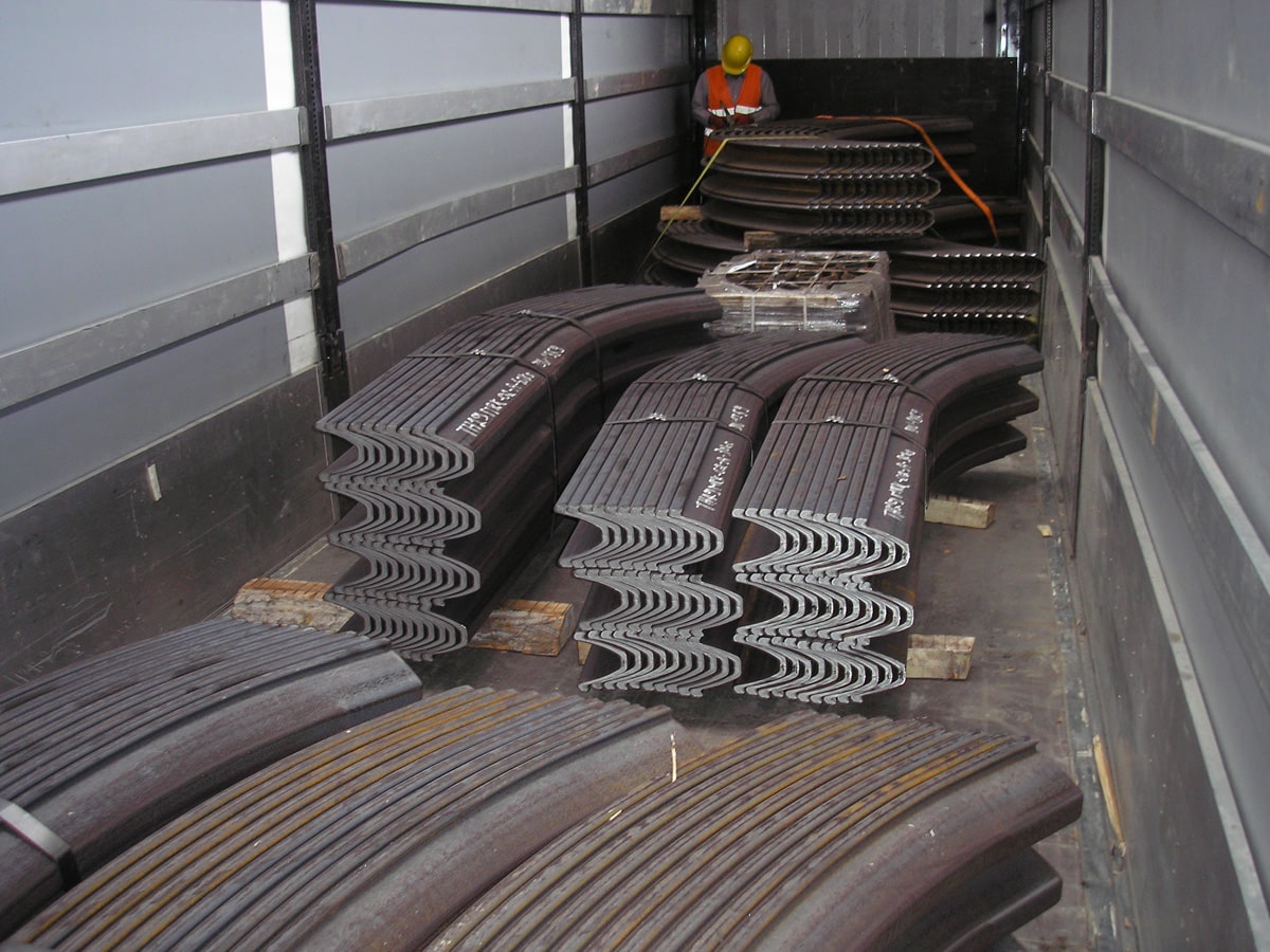
The support of mine drifts and tunnels using THN Steel Arches offers significant advantages in environments subjected to high ground pressure.
This system combines the high load-bearing capacity of the steel profile with a key feature: the sliding behavior of the support set. Unlike traditional rigid arches, the Ω arch is designed to yield in a controlled manner when ground pressure reaches a certain threshold.
This controlled sliding prevents premature structural failure of the profile, reduces the risk of breakage, and acts as an indicator of the stress level affecting the excavation.
The Ω arch does not resist ground pressure through absolute rigidity, but through intelligent balance: it yields when necessary and provides support when required.
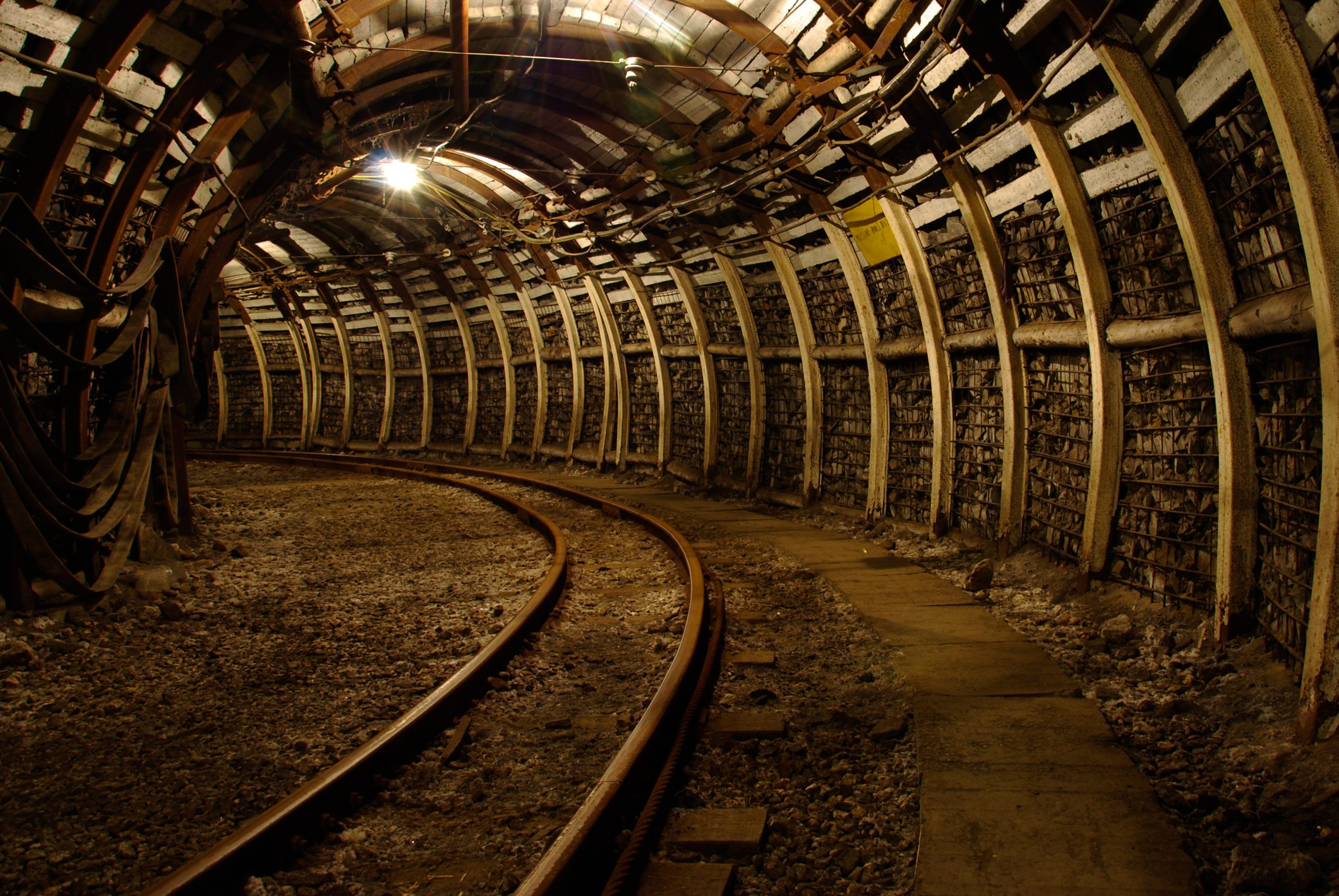
The first characteristic to highlight of THN Sliding Steel Arches is the geometry of their profile. This section presents an almost equivalent resistance to loads acting along both principal axes, transverse and longitudinal.
From a mechanical perspective, the relationship between the section modulus about the X-axis and the Y-axis is approximately equal to 1:
Wxx / Wyy ≈ 1
This structural symmetry allows the profile to perform in a balanced manner under ground deformation, enabling large convergence of the tunnel or drift section without compromising its load-bearing capacity.
Main Advantages of THN Steel Arches
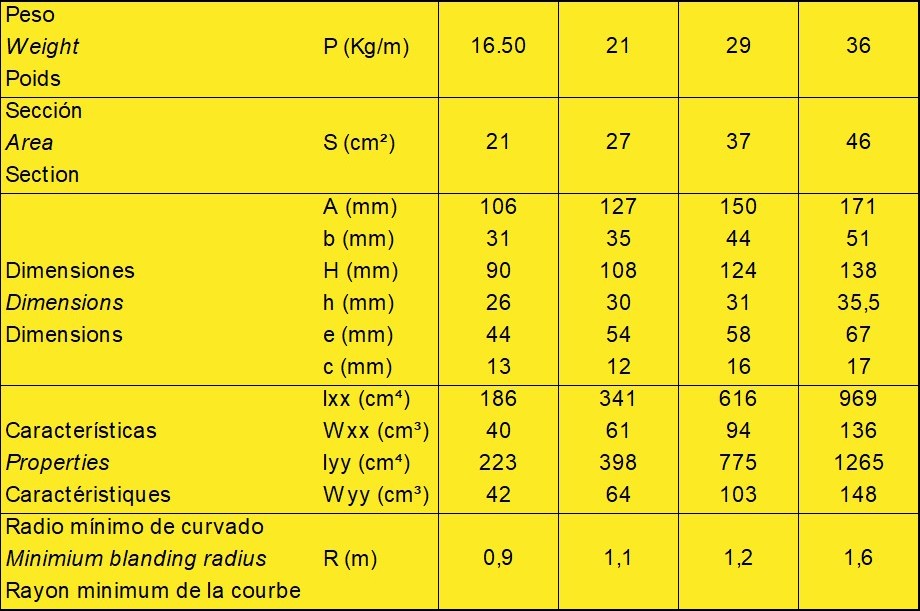
Mechanical Properties of the Ω-Type Profile
The following table presents the mechanical properties of the Ω-type profile in its different commercial configurations.

Beyond the mechanical properties of the profile —which will be analyzed in more detail later— another key aspect of Ω-type arches is their initial assembly configuration.
The different arch segments are connected using clamps rather than welds. These clamps allow a certain degree of controlled sliding —depending on the selected type— which constitutes the distinctive feature of this support system.
The design of THN Sliding Steel Arches allows for simple and rapid installation, while also providing better adaptation to the excavated section compared to traditional rigid arches. As a result, the effective cross-section of the tunnel or drift is optimized.
Another relevant advantage compared to fixed arches is the possibility of recovery once their structural function has been fulfilled. In certain mining operations, the sets can be dismantled and reused, helping to optimize operational costs.
Regarding the bending of the profile, direct bending is typically used in mining applications, whereas inverse bending is more common in civil tunneling, particularly in the New Austrian Tunnelling Method (NATM). In this case, the web of the profile may be perforated to allow its combination with rock bolts, enabling the arch to mobilize load together with the surrounding ground. Thanks to the adjustable overlap between arch segments —increasing or decreasing their effective length— the set adapts to the excavation before becoming embedded in the shotcrete lining.
With this system, it has been possible to meet the requirements of mining operations with increasingly larger tunnel sections and greater depths, where ground pressures are significantly higher. In such scenarios, the design of the connection system, the permitted degree of sliding, and the proper placement of the clamps become determining factors in the structural performance of the support system.
Design Assumptions for Support System Dimensioning
For the calculation of the required ground support in a drift or tunnel using Ω-type arches, the following simplified assumptions are adopted:
- Structural behavior: the steel arch is considered a structure with pinned supports at its bases.
- Load model: the loads acting on the arch are assumed to be vertical and uniformly distributed.
- Failure mode: failure of the steel set is assumed to occur due to bending, neglecting the effects of combined bending and axial forces.
In the case of sliding sets, axial sliding at the joints must occur before bending failure is reached. - Allowable stress: in mining —and also recommended in civil tunneling— the maximum allowable stress is taken as the ultimate tensile strength of the steel used.
Design Charts for THN Sliding Steel Arches
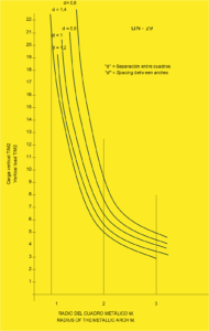
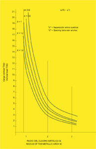
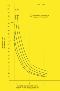
Based on these assumptions, design charts can be developed for the commercial profiles Ω-16.5, Ω-19 and Ω-21, which facilitate the preliminary dimensioning of the support system.
The procedure is straightforward:
-
On the horizontal axis, the radius of the steel set is introduced (equivalent to half the width of the drift or tunnel).
-
On the vertical axis, the estimated vertical load (t/m²) is introduced.
As a result, the recommended spacing between steel sets (support spacing) can be obtained.
Clamping Systems and Installation Recommendations
A fundamental aspect of the Ω system is the design and performance of the connection clamps, which determine the degree of sliding and the overall structural behavior of the support set.
Different types of clamps are available depending on the required tightening level and the desired degree of sliding in the installation. As a general guideline, a minimum overlap between arch segments of 400–500 mm is recommended.
The recommended minimum tightening torques (kg·m) are as follows:
Ω-16.5: 25–30 kg·m
Ω-21: 25–30 kg·m
Ω-29: 35–40 kg·m
Ω-36: 40–45 kg·m
Installation Guidelines for THN Sliding Steel Arches
During installation, the following aspects should be taken into account:
-
Ensure parallelism of the profiles in the overlap zone.
Misalignment prevents proper sliding and may cause structural failure or unwanted deformation. -
Ensure that the arch remains perpendicular to the axis of the drift or tunnel.
-
Do not clamp profiles with defective or false overlaps, meaning situations where proper contact between both segments is not achieved.
-
Respect the specified tightening torques.
The use of pneumatic tightening tools facilitates achieving the correct torque and ensures uniform installation. -
Once ground pressure begins to act on the arch —which can be observed through compression of the packing or lagging— and the first sliding occurs, it is recommended to retighten all connection nuts.
Technical Note
The values and recommendations presented above are indicative and should not be considered as definitive design criteria. Support system dimensioning must consider the complete set of geotechnical and structural conditions of each project.
At Onix Underground, we understand that underground support design is not defined solely by calculations or theoretical models, but by its ability to effectively respond to real excavation conditions.
For this reason, our approach to support systems using THN Sliding Steel Arches is based on three fundamental pillars:
-
Rigorous technical design, based on real geotechnical data, structural criteria, and experience in complex ground conditions.
-
Controlled installation, where the proper assembly of the system —arch geometry, clamp type, degree of sliding, and spacing between steel sets— is critical to the overall performance of the support.
-
Operational efficiency and safety, integrated into every technical decision to ensure ground stability, excavation continuity, and protection of operations.
Our approach is focused on minimizing geotechnical risk, optimizing support performance, and adapting the system to the real conditions of the rock mass, both in underground mining and civil tunnelling projects.
Each solution seeks the balance between structural strength, deformation capacity, and construction efficiency, which are key factors in excavations subjected to convergence and high ground pressures.
Because in underground engineering, ground support is not just a structure: it is the element that makes excavation safe, stable, and operationally viable.
